

This article follows on from my previous articles about the Arduino microcontroller; Sketch 1: Light Switch and Sketch 2: Light Sensor. In this article I cover an analogue sound sensor with LEDs displaying for the loudness (noise level) of the sound detected.
I purchased a multi-pack of sensors a while back and there was a small sound and big sound sensor in that pack. I can’t remember the seller but there are plenty on Amazon and eBay. If you want the one I’m using in this example, you can find it here, Sound Detection Module For Arduino.
You will note that it has 4 pins. Two are for the current but the other two are for digital or analogue outputs. If you have one with 3 pins then it is likely to be the digital only module. Digital can be set to a threshold and returns high or low depending on the level of sound going above or below the threshold. I’ve not tried this. The analogue output shows the loudness of the sound detected. However, you should note the sensing range of this microphone is very small, probably about an inch so it has to be very close to the sound source to work. There are probably better microphones but I wanted to work with the sensors that I had. Big the big and small 4 pin sensors work the same way so in this article I am only using the big one.
I’ll get straight into it. Once again, I’m using an Arduino and I’ll lay out the article in the same format as previously with diagrams using Fritzing software. So here goes.
Sketch 3: Sound Sensor
Objective: Use a sound sensor to illuminate a series of LEDs based on the loudness of the sound.
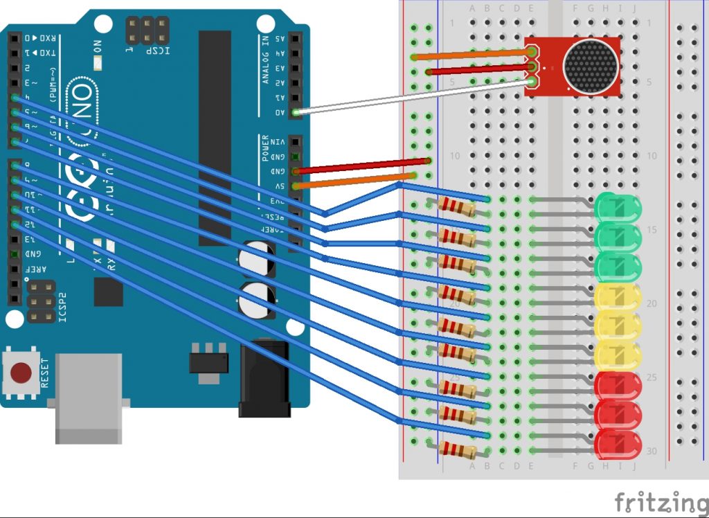
Requirements: Arduino (and USB cable), Solderless Breadboard, 9 LEDs (3 red, 3 green and 3 yellow), Analog Sound Sensor, 9 Resistors (220 Ohm) and wires. And something to make a noise to test it.
Design (note that Fritzing didn’t have the sound component that I was using so I subbed it for the 3 pin one shown with the white wire going to analog port A0):
Schematic:

Code:
const int soundPin = A0;
const int firstLEDPin = 4;
const int ledCount = 9;
int soundSample;
int maxQuietRange;
int ledThreshold[ledCount];
void setup() {
// setup the analogue input
pinMode(soundPin, INPUT);
// setup LEDs
for(int i=0;i<ledCount;i++)
{
pinMode(firstLEDPin+i, OUTPUT);
}
// test LEDs
for(int i=0;i<ledCount;i++)
{
digitalWrite(firstLEDPin+i,HIGH);
delay(100);
}
for(int i=0;i<ledCount;i++)
{
digitalWrite(firstLEDPin+i,LOW);
delay(100);
}
// setup the serial monitor
Serial.begin(9600);
// get initial sound value for max range
soundSample = analogRead(soundPin);
maxQuietRange = soundSample;
// test whilst it’s quiet
Serial.println(“Looping 100 times until we have a stable maximum silent value.”);
for(int i=0;i<100;i++)
{
soundSample = analogRead(soundPin);
if (soundSample > maxQuietRange) maxQuietRange = soundSample;
Serial.print(“Max Quiet Range = “);
Serial.println(maxQuietRange);
delay(10);
}
// set the threshold for the LEDs to display over the maximum quiet value
// incremented by one for each LED
for(int i=0;i<ledCount;i++)
{
ledThreshold[i] = maxQuietRange+i+1;
}
}
void loop() {
// listen out for sounds that go above the max quiet sound range
soundSample = analogRead(soundPin);
// illuminate LEDs above the threshold
for(int i=0;i<ledCount;i++)
{
if(soundSample>ledThreshold[i])
{
digitalWrite(firstLEDPin+i,HIGH);
delay(10);
}
}
// turn the LEDs off before starting again
for(int i=ledCount; i>1;i–)
{
digitalWrite(firstLEDPin+i,LOW);
}
}
Setup Explanation
The shorter LED leg connects to the negative side of the current (Ground). You use a 220 amp resistor so you don’t overload the LED with current. The positive leg connect to digital channels 4 to 12 on the Arduino in order. Starting with the green LEDs for completely safe noise levels through yellow for “could be risky” to red to show a dangerously high noise level.
Three of the four pins on the sound sensor are used. They are marked so you can see which connects to which. We are not using the “D” pin so only ground, current and analog need connecting. Analog to pin A0 on the Arduino and ground to negative and current to positive 5V.

Code Explanation
The code is split into three parts; the setup, the loop and some variables and constants set outside of them at the top. The constant is for the analog channel to use. Constants and variables assigned outside of the setup and loop functions stay in memory and can be called by either setup or loop or any other functions. Constants don’t change during the lifetime of the code execution where variables could change.
The next two constants are for the digital pin number of the first LED and how many LEDs we will use. This is because we’ll automatically assign the 9 pins during setup. There are also three integer variables that will get their values during setup but are declared here so they are available for the loop too.

The setup section runs some tests and setup the variables to be used. First it sets the mode of A0 to input. Then loops through the 9 LEDs assigning their digital pins starting with the first pin connected to 4. It then tests that it can light up and then switch off all of the LEDs.
Then a serial monitor port is set up in case you want to see the values of the next sound range test. It reads the analogue input and then checks it 100 times each with a hundredth of a second delay. Any time it finds an input value that is higher than previously found then it set the maximum quiet range to that higher value.
Finally, it adds values to the threshold for each LED. Starting with the first green one using pin 4, it allocates one high than the maximum “silent” value.

The loop listens for sounds and if those sounds are above an LEDs threshold, it will illuminate that LED. Each LED is checked in turn with a hundredth of a second delay between each check. After all have been checked and illuminated if necessary, all are turned off in the opposite order to give a rise and fall effect.

Final Step
If you have been trying this for yourself, the final step is to upload the code to the Arduino through the USB Cable but make sure you have the right COM Port selected from the Tools menu before uploading.
You should do this when it is quiet and the noise levels that you want to test are not close by. This is because the setup process has to work out what a typical noise level is.
Example Pictures
I tried various noises. Most illuminated one or two green LEDs, even a clap only got three. I had to play rock music close by to get into the yellow. When I slapped my hand down hard on my desk, making a deafening bang, it shot all the way to the last red.
Example Rock Music Detected:

Example Loud Bang Detected:

Last Word
The sound sensor itself cannot pick up sounds further than a few inches away. I think it’s range is probably 6 inches but I found you had to make a noise much closer to get a good response.
The sound sensor converts sound to voltage and that is what comes through the analogue channel. I didn’t try but you may get different or better results at 3.3 volts.