

I’ve been meaning to follow up my previous getting started with the Arduino microcontroller article for a while now. Quite a long while as it’s almost three years. The other reason for writing this now is that my first article has been visited quite a lot recently, so I wanted to add to my electronics section.
At the end of my last article I asked for suggestions of what to build next but didn’t have any responses. I thought I’d make a variation on my light switch example and have the light turn on when it starts to get dark and proceed to get brighter the darker it became. As it happens, I’m doing this at night and the lighting is not very good so the LED actually comes on in my room even with the light on. If you have a similar situation then you can either move the photo sensor closer to the light source or you use a torch to show that it works.
I’ll get straight into it. Once again, I’m using an Arduino and I’ll lay out the article in the same format as previously with diagrams using Fritzing software. So here goes.
Sketch 2: Light Sensor
Objective: Use a photo sensor to switch on a light (LED) when it gets dark (with brightness adjusted for dimness).
Requirements: Arduino (and USB cable), Solderless Breadboard, Yellow LED, Photosensor, 10K Ohm Resistor, 220 Ohm Resistor and wires. Possibly a torch.
Design:

Schematic:

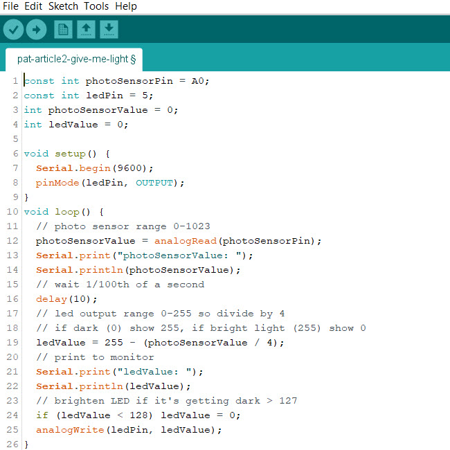
Code:
const int photoSensorPin = A0;
const int ledPin = 5;
int photoSensorValue = 0;
int ledValue = 0;
void setup() {
Serial.begin(9600);
pinMode(ledPin, OUTPUT);
}
void loop() {
// photo sensor range 0-1023
photoSensorValue = analogRead(photoSensorPin);
Serial.print(“photoSensorValue: “);
Serial.println(photoSensorValue);
// wait 1/100th of a second
delay(10);
// led output range 0-255 so divide by 4
// if dark (0) show 255, if bright light (255) show 0
ledValue = 255 – (photoSensorValue / 4);
// print to monitor
Serial.print(“ledValue: “);
Serial.println(ledValue);
// brighten LED if it’s getting dark > 127
if (ledValue < 128) ledValue = 0;
analogWrite(ledPin, ledValue);
}
Example in dim light:

Example in bright light:

Setup Explanation
The shorter LED leg connects to the negative side of the current (Ground). You use a 220 amp resistor so you don’t overload the LED with current. The positive leg connect to digital channel 5 on the Arduino.
The photo sensor legs are both the same size and it doesn’t matter which way around you have them. It requires a 10 kiloamp resistor to the negative current and also a connection on this side to an analogue channel (A0 on the Arduino). The other side of the photo resistor connects to the positive current.
Code Explanation
The code is split into two or three parts; the setup, the loop and some variables and constants set outside of them at the top. The two constants are for the channels to use of the Arduino and the two variables for the settings based on the light (one for input and one for output).
The setup section opens and sets the serial monitor to 9,600 Baud. It then sets the pin mode to output for digital channel 5.
The loop section is well commented and even sends some print statements to the serial monitor if you have that running. I’ll explain what is happening within the loop. The value of LED brightness is read from the photo sensor from a range of 0 (completely dark) to 1023 (completely bright). The LED accepts a range of 0 (off) to 255 (very bright). We therefore divide the photo sensor value by 4 to get in the range of the LED. It takes a microsecond or two to get the analogue reading so we’ve added in a hundredth of a second delay. The brightest value is not any good for our purpose as we want the LED to come on if it is dark so we have to take the result away from 255. If it is completely dark, it will be 0 and so we want to set the LED to 255. If it is completely bright 255 we want the LED to be set to 0.
Once done we will get an indication of how bright the LED needs to be to replace the darkness. However, we don’t want to use the LED if its illumination is not required. Therefore, we set the threshold for switching the LED on only if the brightness value needs to be between 128 and 255.
Finally
When I tried it, there wasn’t enough light so it stayed on. I used a torch on the photo sensor and that switched the LED off.
If you have been trying this for yourself, the final step is to upload the code to the Arduino through the USB Cable but make sure you have the right COM Port selected from the Tools menu before uploading.