This is my first article about the Arduino microcontroller development board and indeed my first article in my new Electronics category. I am fairly new to this but filled with excitement as I delve into another hobby and perhaps a second childhood (or maybe a fifth or sixth). I say that because I have always had a keen interest in both electronics and programming and the Arduino mixes both of these interests. As a child, having an Arduino, would have saved many an electronic device from being “upgraded” by my small hands.
I like to know how things work and then attempt to improve it. From my early childhood and into adulthood, many items from video recorders, radios and televisions to electric heaters, washing machines and household lighting have been dismantled and put back together. There has been the occasional mishap (like ending up with spare parts left over or a complete device failure) but I’ve also fixed many devices and improved one or two as well. I’ve also been very interested in programming stretching back to my school days creating work routines and some simple games using the Sinclair ZX81, BBC Micro and Apple 2. So if the Arduino had been around when I was younger I could have satisfied some of my electronics curiosity and programming experimentation. My parents (and friends) would have been delighted that I wasn’t testing my theories on their electrical devices.
In this first article I want to introduce the Arduino but I know there is already a wealth of resources available on the internet so I’ll keep this brief but you’ll have everything you need to know to get started.
I purchased the Arduino Starter Kit from Amazon and ran through most of the projects in the book from that kit. What I like about it, is that you get everything you need to get experimenting straight away. The breadboard allows you to experiment and prototype without soldering and in the Arduino starter kit you also get a base to keep your Arduino and breadboard together which comes in very handy.
I was also running through these projects with my kids and my youngest son actually raced ahead and did a couple of projects on his own. It’s funny that one of them likes programming and the other electronics. Since then my electronics stores have since grown as I have read more books and experimented with different types of inputs and outputs.
Towards the end of 2015, I was thinking of writing something about the Arduino on my blog but I didn’t know how best to express that on a page in a diagram rather than as a photograph. I was thinking of writing an application to replicate the Arduino Uno with a half-sized breadboard (as you get in the starter kit) and the components. Then I noticed a diagram that had been put together by someone using the open source project from Fritzing. I made my donation which was optional and downloaded a copy. It was perfect for diagramming my intensions before actually putting it together and for keeping a copy of my designs on the computer for future reference but also for my purpose of adding to my article. It did everything I had envisaged and a lot more. You can also publish your designs on their website.
Getting started
Anyway for this first article, I wanted to do something simple but not the same as the starter guide from the kit or even anything I had seen before (although I’m sure someone somewhere will have done something similar already). So, in this example we will make an on-off light switch.
Before we delve into that let us clear a few things up. In Arduino Language, the design is called a sketch. The Arduino itself is a circuit board with a microprocessor that can interact with the outside world through extending it with sensors (inputs) and actuators (outputs). It can be used to provide power to electrical components on a solderless breadboard or a prototype shield or can be used to send, receive and process electronic signals from its many ports. The Arduino itself can be powered by a 9V battery or by a USB cable. The USB cable is also used on a computer to monitor the Arduino and to upload programming instructions. There is a programming IDE for the Arduino that can be found at Arduino IDE Download.
So here we go, everything you need for the project should be found below.
Sketch 1: Light switch
Objective: Use a button to switch on or off an LED.
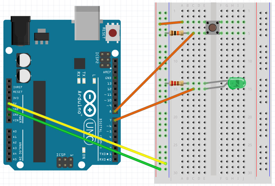
Requirements: Arduino (and USB cable), Solderless Breadboard, Green LED, Push button switch, 10K Ohm Resistor, 220 Ohm Resistor and wires.
Design:
Schematic:
Code:
int switchState = 0;
int testState = 0;
int LED = 7;
int Button = 8;
void setup() {
pinMode(LED, OUTPUT);
pinMode(Button, INPUT);
}
void loop() {
testState = digitalRead(Button);
if (testState == HIGH) { // has the button been pressed
switchState = abs(switchState-1); // take the absolute value (1 or 0) by changing the switch state (-1)
digitalWrite(LED, switchState); // apply the switch state to the LED
}
delay(500); // delay half a second before next check (loop)
}
Example:
Explanation
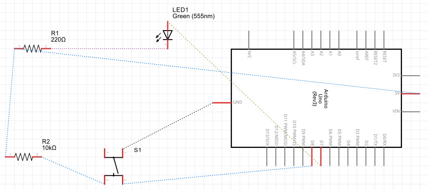
The LED will have one leg longer than the other and the shorter leg needs to connect to the negative side of the current (Ground). You use resistors to reduce the current to components. The LED for example will have a significantly reduced lifespan and burnout if you do not limit the current flow. Some components require higher current and you can use capacitors or another power source for that but they are not used in this example. The double slash indicates that everything after it on a line is a comment and should not be processed.
The code is split into two or three parts; the setup, the loop and optionally any variables or functions set outside of the setup and loop. For example if you need a variable to be used in setup and loop then you would define it outside of both. If you define something just in the scope of the setup or loop then it will only apply to that section.
A variable is a named storage space in memory that you can alter throughout your code as and when you need to (i.e. it can be variable). In the code I have set the switchState and testState variables as integers and assigned then a zero value which is equivalent to “off” or low voltage. The opposite state will be 1 which is the same as “on” or high voltage.
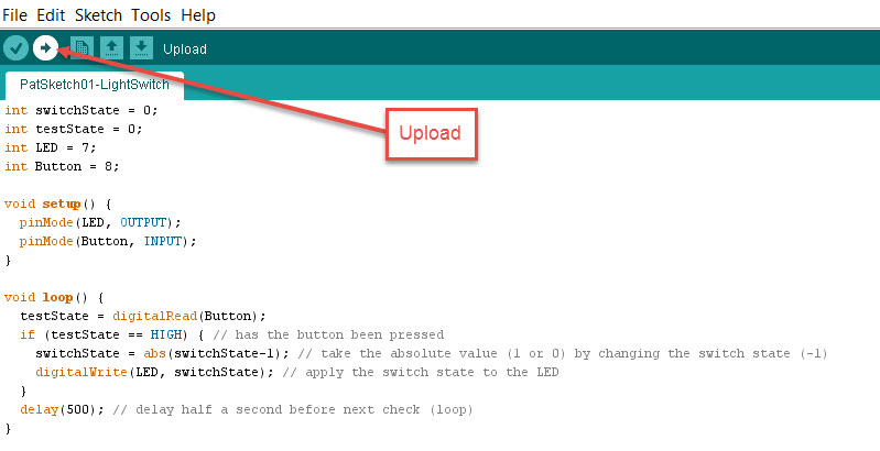
You upload the code to the Arduino through the USB Cable but make sure you have the right COM Port selected from the Tools menu before uploading.

The setup section runs once when the Arduino is powered on or when you have uploaded some new code. The startup sets the pins on the Arduino board that we are using for our button input and our LED output. After setup the loop section fires up and runs continuously. I’m not sure of the frequency but it is at least once every millisecond (thousandth of a second). In here we test to see if the button has been pressed and if the voltage is HIGH (equivalent to 1 or “on” or “true”) then it changes the switch state to either 0 or 1 by taking 1 away from its current value and using the absolute to convert -1 to 1 (a little trick rather than typing out something like “if switch state is 1 then set switch state to 0 otherwise set switch state to 1” which would also work). I then pass the switch state value (1 for HIGH or 0 for LOW) to the LED.
Lastly I set a half of a second delay before going through the loop again. This gives the Arduino a chance to change the bulb state and for you to release the button. If you push the button and release too quickly the state will have a chance to change. If you keep your finger on the button and don’t release within half a second, the state will change again and the LED will go back to its original state.
So that’s it for now. I will write some more Arduino articles in the future but it’s hard to think of simple things to demonstrate that haven’t already been done. Perhaps I should broaden my scope, so if you have any ideas for sketch challenges that haven’t been done elsewhere then let me know.
